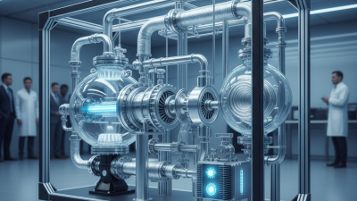
A Cryo Refrigerator is more than a machine that makes things cold. It is a carefully controlled system for producing and maintaining extremely low temperatures. These temperatures may fall below -150°C, depending on the design and application. Laboratories, medical facilities, space programs, and quantum technology companies all use this equipment.
Heike Kamerlingh Onnes, a pioneer of low-temperature physics, used the phrase, “Through measurement to knowledge.” That idea still guides cryogenic engineering today. A Cryo Refrigerator removes heat through staged cooling. Compressors, heat exchangers, expansion devices, and special refrigerants work together. The system may begin with room-temperature gas. It gradually cools that gas through repeated compression and expansion. At the cold end, the refrigerator can cool sensors, superconducting magnets, or stored samples.
The process sounds simple. It is not. Small heat leaks can raise the temperature quickly. Door seals, electrical wires, vibration, and even careless handling may affect performance. Many systems also require vacuum insulation, because ordinary air transfers unwanted heat. Real equipment is never perfectly efficient. That limitation matters.
This guide will explain how a Cryo Refrigerator works, what its main components do, and why maintenance requires precision. It will also examine common cooling methods, operating challenges, energy demands, and safety considerations. Some explanations may simplify complex physics. That is intentional, but readers should still question easy answers. Low-temperature engineering rewards careful measurement, practical experience, and respect for details that are easy to miss.
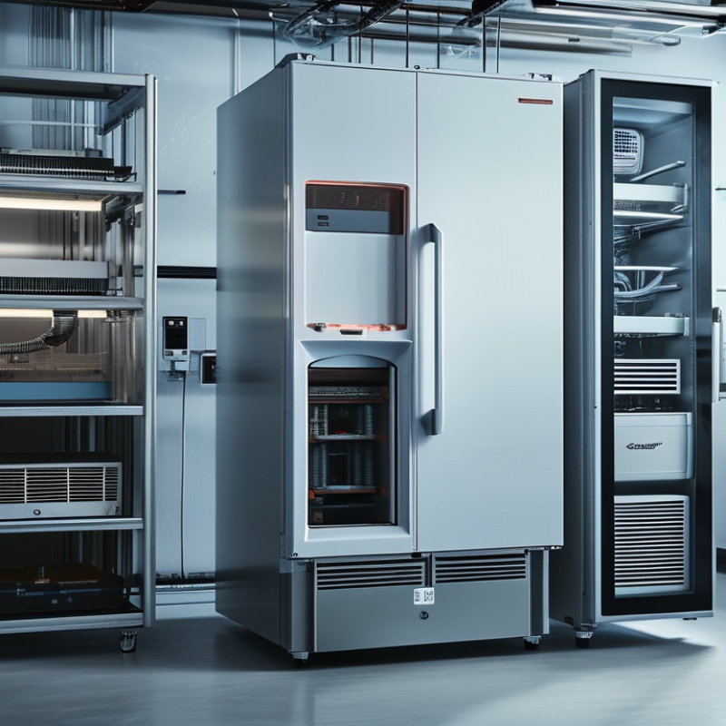
A cryogenic refrigerator is a mechanical cooling system designed to reach extremely low temperatures. The boundary is not perfectly fixed. In engineering practice, cryogenic operation often means temperatures below about 123 K, or -150°C.
Some specialized systems reach below 1 K with additional cooling stages.
Its scope extends beyond simple refrigeration. Cryogenic refrigerators support sensor calibration, infrared detection, quantum experiments, medical research, and materials testing. They usually remove heat through repeated compression and expansion of a working gas. A compressor sends high-pressure gas into a cold head, where heat exchangers and expansion spaces reduce its temperature. Pulse-tube, Stirling, Gifford-McMahon, and Joule-Thomson designs use different flow patterns and components. The result is a controlled cold surface, often inside a vacuum chamber.
Temperature stability matters as much as the lowest temperature. A system rated for 4 K may perform poorly under heavy heat loads, vibration, or frequent door openings. Engineers therefore examine cooling capacity, cooldown time, electrical demand, and maintenance access.
Small leaks can create ice near seals. That detail is easy to underestimate.
Actual performance also depends on insulation quality, radiation shields, sample wiring, and measurement accuracy.
In my view, the operating range should always be reported with its heat load and test conditions, not as a single impressive number.
What Is a Cryo Refrigerator and How Does It Work?
A cryogenic refrigerator removes heat from gases, sensors, or superconducting equipment. NIST data lists nitrogen’s boiling point at 77.355 K and helium’s at 4.222 K. Reaching such temperatures requires several coordinated components, not one magic cooling stage.
The compressor raises helium pressure and sends hot gas through an aftercooler. A counterflow heat exchanger then transfers heat from the high-pressure stream to returning cold gas. The expander lowers pressure and extracts work, producing a strong temperature drop. Some systems use turbines, while others use pistons or pulse-tube arrangements. The regenerator stores heat during one flow direction and releases it during the reverse direction. ASHRAE Handbook—Refrigeration identifies heat exchangers and regenerators as central elements in cryogenic systems. Small leaks matter. Even a minor pressure loss can reduce cooling capacity and increase operating time. In practice, I would question any efficiency claim without its temperature, load, and input-power conditions.
Tips: Inspect insulation, seals, and vibration regularly. Compare performance at the actual cooling load, not an ideal laboratory point. NIST reference values help verify temperature sensors, but calibration errors still occur. Keep a maintenance log. It may reveal a slow decline before failure becomes obvious.
| Core Component | Primary Function | How It Works | Typical Operating Characteristics | Design Considerations |
|---|---|---|---|---|
| Compressor | Raises the pressure of the working gas and supplies the input power for the refrigeration cycle. | The compressor receives low-pressure gas, compresses it, and sends higher-pressure gas toward the heat-rejection and expansion sections. | Closed-cycle systems commonly operate with pressure ratios of roughly 2:1 to 10:1, depending on the cycle, gas, and target temperature. | Compression generates heat, so oil management, vibration control, sealing, cooling, and gas purity are important. Helium is widely used when temperatures below approximately 100 K are required. |
| Expanders | Produce refrigeration by allowing high-pressure gas to expand and decrease in temperature. | In a turboexpander, gas performs work on a turbine. In a reciprocating or regenerative expander, gas expands through a piston or displacer-based process. | Expansion can reduce gas temperature from near-ambient conditions to below 100 K in suitable systems; specialized cryocoolers can reach approximately 4 K. | The expander must minimize heat leakage and mechanical losses. Turbine expanders require clean gas and precise high-speed bearings, while reciprocating designs require reliable seals and moving clearances. |
| Heat Exchangers | Transfer heat between incoming and returning gas streams without mixing them. | The warm high-pressure stream is precooled by the cold low-pressure return stream. Counterflow arrangements are commonly used to maximize temperature effectiveness. | Cryogenic heat exchangers may operate across temperature spans from approximately 300 K down to tens of kelvin, depending on the refrigerator architecture. | High effectiveness, low pressure drop, compact construction, and low axial heat conduction are essential. Common forms include plate-fin, tube-in-tube, and coiled-tube designs. |
| Regenerator | Temporarily stores and releases thermal energy to improve heat recovery during alternating gas flow. | A porous matrix absorbs heat from the gas during one part of the cycle and returns heat during the reverse-flow part of the cycle. | Regenerators are especially important in Stirling and Gifford–McMahon refrigerators, where the gas flow direction changes periodically. | The matrix needs high heat capacity, suitable thermal conductivity, low flow resistance, and low unwanted gas mixing. Fine metal screens, stacked foils, and porous materials are commonly used. |
| Cold Head | Provides the low-temperature surface where the useful cooling load is absorbed. | The cold head contains the expander, regenerator, or expansion valve and transfers refrigeration to the protected component through a cold-stage interface. | Typical first-stage temperatures are near 40–80 K, while second stages may operate near 4–20 K in multistage systems. | Thermal shields, multilayer insulation, low-conductivity supports, and flexible thermal links help reduce parasitic heat loads. |
| Working Gas | Acts as the circulating fluid that transports heat through the refrigerator. | The gas is compressed, cooled, expanded, and returned through the heat-recovery section in a repeating closed cycle. | Helium is common for low-temperature closed-cycle refrigerators because it remains gaseous at temperatures where many other fluids condense or freeze. | The gas must be dry and clean. Contamination can freeze in cold sections, restrict flow passages, reduce heat-transfer performance, or damage valves and expanders. |
| Thermal Insulation and Shields | Limit heat entering the cold stages from the surrounding environment. | Radiation shields, vacuum insulation, low-conductivity supports, and staged temperature intercepts reduce radiative, conductive, and convective heat transfer. | A high-vacuum enclosure is commonly used to suppress convection around components operating below ambient temperature. | Even small heat leaks can significantly reduce cooling capacity at very low temperatures, so wiring, supports, seals, and interfaces must be carefully designed. |
A cryo refrigerator removes heat continuously instead of consuming a stored cryogenic liquid. A compressor circulates helium through heat exchangers, valves, and an expander. The gas cools during expansion, then returns through the circuit. Heat exchangers recover cold from the returning gas. This closed-cycle design reduces handling risks and supports long operating periods.
The temperature targets are physical milestones. NIST data lists nitrogen’s boiling point near 77.4 K at one atmosphere. Hydrogen boils near 20.3 K, while helium boils near 4.2 K. Reaching 77 K usually requires precooling and regenerative heat exchange. Reaching 20 K needs additional expansion stages or a dedicated cold head. The final 4.2 K range demands extremely low parasitic heat leakage. Tiny wiring, radiation shields, and imperfect seals matter.
Cooling power falls sharply at lower temperatures. The ASHRAE Handbook on refrigeration describes this trade-off in cryogenic systems: a refrigerator may provide useful watts near 77 K but only fractions of a watt near 4 K. That difference changes equipment sizing. It also changes expectations. A laboratory load that seems insignificant at room temperature can overwhelm a 4 K stage. The simplified picture is helpful, but incomplete. Real systems rarely hold exact target temperatures under changing loads. Measurement uncertainty, vibration, and compressor efficiency still require careful review.
Nominal cryogenic temperature stages reached by closed-cycle cooling systems
Closed-cycle cryogenic refrigerators use compressors, heat exchangers, and expansion processes to remove heat without continuously consuming cryogenic fluids. Typical cooling stages approach 77.36 K using liquid-nitrogen temperatures, 20.28 K using liquid-hydrogen temperatures, and 4.22 K using liquid-helium temperatures at approximately 1 atm. Lower temperatures generally require multiple refrigeration stages and increasingly efficient thermal isolation.
A cryo refrigerator removes heat through staged temperature reduction, not one dramatic cooling step. The first stage often reaches about 40–80 K, using compressed helium in a pulse-tube or Stirling cycle. A second stage can approach 4 K, close to liquid helium’s 4.22 K boiling point at standard pressure, according to NIST thermophysical data.
The refrigerant usually remains gaseous inside the machine. Helium is common because it stays chemically stable and performs well at very low temperatures. Nitrogen may support the warmer stage, with a normal boiling point near 77.36 K. The 2022 ASHRAE Handbook—Refrigeration identifies these boiling points as key reference values for cryogenic system design. Real systems also use regenerative heat exchangers, compressors, valves, and multilayer insulation. Small leaks matter.
Heat loads shrink sharply as temperature falls. A shield near 50–80 K may handle several watts, while a 4 K stage often manages only fractions of a watt. Detector wiring, radiation, vibration, and imperfect supports can consume much of that budget. CERN’s LHC cryogenic design reports illustrate this scale, with cold-mass heat loads measured in fractions of a watt per metre at temperatures near 2 K. That figure is not universal. It changes with geometry, cycling, and equipment duty.
In practice, engineers measure every thermal path. A cable that feels insignificant at room temperature may become expensive at 4 K. The weakest assumption can dominate performance.
A cryo refrigerator removes heat at extremely low temperatures, often below 120 K and sometimes near 4 K. Its performance depends more on measured conditions than on headline specifications. The coefficient of performance, or COP, equals cooling capacity divided by electrical input. For a 4 K system producing 1 W while consuming 5 kW, the COP is only 0.0002. This sounds poor, but it reflects the severe thermodynamic challenge. ASHRAE’s 2022 Refrigeration Handbook and recent International Cryocooler Conference proceedings report similar low-temperature trends.
Cooling capacity must be stated with temperature and operating pressure. A unit may provide several hundred watts at 77 K, yet only about 1 W at 4 K. Small temperature changes matter. A laboratory measurement can also differ from field performance because of radiation, wiring, vibration, and imperfect insulation. The numbers are not always clean.
Hold time describes how long a cryogenic load remains within its permitted temperature after cooling stops. A well-insulated vessel may hold for days, while frequent access can reduce that period sharply. Efficiency should therefore include the complete system: compressor power, cooling water, controls, and maintenance. NIST cryogenic guidance stresses that parasitic heat leaks can dominate the budget. In practice, a 10% insulation improvement may matter more than a higher advertised COP. I would still question any comparison that omits ambient temperature and test uncertainty.